|
previous tutorial |
ACG home |
Instructor home |
Class home |
List of tutorials |
next tutorial |
For the antiquarians in the audience, we have older versions of this tutorial, using:
|
VectorWorks 8 |
MiniCAD 7 |
Strata StudioPro 2.5 |
Strata StudioPro Blitz 1.75 |
Before beginning the project
- If you are working in the ACG Lab
click to read these important notes before you start the tutorial.
This section of the directions contains information that pertains specifically to the way the ACG Lab operates. It may not apply if you work on the project elsewhere.
- If you need to get for yourself the programs mentioned in this tutorial:
- Art of Illusion is an open source program, freely downloadable at www.artofillusion.org.
This program will run on a variety of other computers besides Macintoshes.
Since the 3D software marketplace is very fragmented, there is no single industry standard for 3D programs.
Art of Illusion is an ideal training tool because it provides a broad cross-section of the features shared by all the major players.
At the same time, it preserves a clean, standardized interface, unlike commercial programs which resort to quirky gadgets--making it hard to reuse what you have learned when you approach a new program.
While the program is simple to use, it is not simplistic. It can be used for serious work, as it has all the capabilities required for the complete 3D workflow:
modeling, rendering, and animation.
In this first phase of our 3D project, we will use the most common modeling tools: we will start from flat 2D shapes, converting them to 3D using two techniques generally available in all 3D programs: extruding and lathing. Later we will work directly with basic 3D shapes called primitives, combining them using boolean operations and reshaping them through mesh editing.
After some initial setup, we can proceed to create the elements in our scene:
Initial Setup
- Reset the program to factory defaults by removing the file '.aoiprefs' (if found) from the Preferences folder inside System Folder.
-
Double-click the Art of Illusion application icon to start the program
- A blank document window appears. It shows four views (Front, Left, Top, and the perspective from Camera 1) of your virtual workspace.
- A blank document window can also be created (when the program is already running) using the File-->New command.
- Save the new document: File-->Save As, enter any filename you want (this document will not be posted on the web site directly). Make sure to save often as you continue to work.
- Use the Scene-->Grids command to display a visual reference (Show Grid), and to automatically align your drawing (Snap to Grid).
- You may also want to lower the number of Snap-to Subdivisions, to make it easier to pick exact alignments.
- To see more of your workspace, change the number above the Front viewport from 100 to 10 (this will zoom out your view, and the grid will appear correspondingly smaller)
- Any other viewports displaying a Parallel projection of the scene (such as Left and Top) can be zoomed in the same manner.
- For Perspective views (such as Camera 1), use the Pan Camera tool with the Control key held down.

return to top
Lathed Pedestal
 Choose the Approximating Curve tool.
- An approximating curve comes close to (approximates) its curve points, while an interpolating curve (created with the program's other curve tool) will go right through all its control points.
- In general, the former is used for drawing, as it yields smooth curves more easily. The latter is used for animation paths, as positioning is more predictable.
 Working in the Front viewport, draw the profile for the pedestal (representing one half of a front view of the finished object) using the Curve tool in a connect-the-dots fashion. To give our pedestal a flat level top, the first two points at the upper end of the curve should align horizontally. The rest of the profile is up to you.
- Click on the dark vertical line in the middle of the grid (the Y axis) to establish the starting point of the profile.
- Click to establish additional vertices and smoothly connect additional line segments. To put a crease in the outline (a corner point), click while holding down the Shift key. Use two consecutive corner points to draw a straight segment.
- To complete the profile, return to a location on the Y axis (snapping to the grid should help you make this an exact alignment), and double-click. An example of a completed profile is shown in the picture above.
- When done drawing, leave the profile selected (red handles are visible at the sides and corners of its bounding box).
- Note that all four views have updated, showing that your drawing exists in 3d space, but has no thickness. When working in a 3d program, it is essential to look at your model from many different directions to verify that it does have the shape you expect.
- Note also that the entry 'Curve 1' has been added to the Object List (in the right margin of the window). In a complex scene, it may be difficult to see some elements of your model, but you can easily select them by clicking on the corresponding entry in this list.
- Choose the Tools-->Lathe command. The Lathe dialog appears, choose the settings as follows:
- "Line through Endpoints" for the Lathe Axis (this is the 'hinge' for the profile as it sweeps through 3d space to define a solid object).
- Total Rotation Angle = 360 (the profile will make a complete circle around the axis)
- Radius = 0.0 (because we don't want a doughnut-like shape with a hole in the center)
- Segments = 8 (this affects the amount of control you have if you later wanted to reshape the object)
- You can click and drag the preview image on the right to rotate it and visually verify the effect of your settings.
- Click <OK> to exit the dialog.
- The result is a symmetrical 3-D shape, with a circular cross-section, based on the 2-D profile you drew earlier.
- All four views again update, showing the new shape in the workspace.
- Note that the entry 'Lathed Object 1' has been added to the Object List.
- Note also that the entry 'Curve 1' is still listed (in case you wanted to create additional objects based on this profile).
Since we don't need Curve 1 now, click on its name to select it, then use Object-->Hide Selection to remove some clutter from the scene (the list entry turns grey to remind you that the object is not visible).
return to top
Extruded Logo
-
Choose the Approximating Curve tool again.
- Now that you have had some practice, try your hand at drawing a more intricate shape: your name's initial letter.
- Because of the way this curve will be converted to 3d, make sure to draw the entire shape of the letter as a single unbroken curve (imagine you are bending a glass tube to make a neon sign).
 Working in the Front viewport, click the sequence of control points to create the shape of the letter. Double-click to set the last point, and a 'Curve 2' entry will be added to the Object List. Leave the curve selected.
- Display the Tube dialog by using the Tools-->Tube command.
- Adjust the Width value based on the preview image.
- Choose whether the tube should be hollow (Open Ends) or solid (Flat Ends).
- Click <OK>
- The result is a tubular 3-D object, with a circular cross-section, bent in the shape of the last 2-D profile you drew.
- The entry 'Tube 1' has been added to the Object List.
- The entry 'Curve 2' was retained. Click on its name to select it, then use Object-->Hide Selection to make it invisible.
- If the object is not quite to your liking, it is easy to make changes to it: the Tube command we used is a simplified form of extrusion, sweeping a preset shape (a circle) along the selected curve.
The advantage to this simplified technique is that the entire 3d object can be reshaped by modifying the few points that make up the curve.
- To adjust the shape of your extrusion, double-click the entry 'Tube 1' in the Object List.
- A new window appears, where you can use the selection tool (the first one at the top of the toolbox) to reposition the control points. If any points are hidden, choose View-->Display Mode-->Transparent.
- To remove a point, click on it to select it, then use the command Tube-->Delete Selected Points.
- To add a point, select two consecutive points (use shift-click to add to the selection), then use the command Tube-->Subdivide Selection. A new point appears between the two you had selected.
- To change a curve point to a corner, click on it to select it, then use the command Tube-->Smoothness. Enter 0 in the Smoothness field and click <OK>. The smoothest curve has Smoothness value of 1. Setting Smoothness to intermediate values adjusts the curvature.
- To taper or inflate sections of the object, select a control point and use the command Tube-->Set Thickness. Enter a new number and click <OK> to alter the segment of the tube influenced by the selected point.
- Click <OK> (at the top-right of the window) to exit Tube editing and apply the changes you made to the model.
return to top
Boolean Subtraction Walls
 Using Object-->Create Primitive-->Cube, insert a box that will become the outside surface of the walls and floor slab of a simple building. In the dialog which appears next, enter a size large enough to enclose the entire scene. Assuming you sized objects roughly as shown in the previous steps, you can use these measurements:
- Enter 0 in all Position and Orientation fields.
- Size X (width) = 15
- Size Y (height) = 15
- Size Z (length) = 15
- Click <OK> to exit the dialog and create the new object. A cube appears in the scene, and the entry 'Cube 1' is added to the Object List.
- Repeat the same process to create a second, narrower and taller box (e.g., 14 long and wide, 16 high).
- The entry 'Cube 2' has been added to the Object List.
 Examine all four views to verify that the two cubes are positioned one inside the other, with the taller one jutting out of the wider one.
Use the Rotate Camera tool to help you look at the model from all sides in the Camera 1 view.
Examine all four views to verify that the two cubes are positioned one inside the other, with the taller one jutting out of the wider one.
Use the Rotate Camera tool to help you look at the model from all sides in the Camera 1 view.
 Next, choose the Move Object tool so that we can adjust the position of the cubes.
- Click in the front viewport (it becomes the current view, as shown by the thick outline that surrounds it)
- Use Scene-->Display Mode-->Wireframe to change the way the objects in the scene are displayed, from smooth (solid) to wireframe
(objects appear transparent because all the edges are displayed). This makes it easier to see overlapping objects.
- Now drag up the taller cube (Cube 2), so that its bottom edge is above the bottom edge of the wider cube. The gap between the bottom faces of the cubes will become the floor slab of the building.
- Verify in all four views that the two boxes are one inside the other, the inner one protruding past the top (but not the bottom) of the outer one.
 Solid modeling lets you create complex shapes by combining simpler ones. In this case, we will use the inner box to subtract (carve out) a cavity in the outer box:
- Click on 'Cube 1' in the Object List, then shift-click on 'Cube 2'. In the case of subtractions, the order in which you select the objects does matter.
- Display the Boolean dialog by using the Tools-->Boolean Modelling command.
- Choose 'First - Second' from the Operation pop-up menu.
- You can drag the preview image to rotate it. Drag it with the Command and Control keys pressed to zoom in and out.
- Click <OK> to complete the subtraction.
- You have created in a single step the walls and floor of a room. Hide the objects 'Cube 1' and 'Cube 2', and you will see clearly the new object, 'Boolean 1'.
-
Use the Move Object tool in the Front viewport to reposition the pedestal so it rests on the floor. Reposition your initial letter as well.
- You can afterwards switch back to a solid view of the objects in the Front viewport with Scene-->Display Mode-->Smooth.
 Now you can cut your choice of doors and windows in the walls of the room by subtracting additional cubes, created either with the Object-->Create Primitive-->Cube command, or by drawing with the Cube tool.

-
Check your work in all four views, and if necessary use the Move Object tool to reposition the cubes as needed.
 If you need to resize the cubes, use the Size fields in the Layout dialog (Object-->Object Layout), or drag a cube's handles (the red dots that surround it when selected) using the Scale Object tool.
 Complete the room with Boolean subtractions:
- Using any Object tool, click on one of the new cubes to select it.
- Shift-click the walls to add them to the selection.
- Display the Boolean dialog by using the Tools-->Boolean Modelling command.
- Choose 'Second - First' from the Operation pop-up menu. Click <OK> to make a 'hole' in the wall.
- A new Boolean item is added to the Object List. Select the old boolean object and the cube you subtracted from it, and use Object-->Hide Selection to make them invisible.
- Repeat the same process for each one of the remaining cubes.
return to top
Triangle Mesh Roof
- We'll use another cube as the initial shape of the roof.
- Using the command Object-->Create Primitive-->Cube display the Cube Layout dialog
- Enter the following measurements (assuming you sized the very first cube as recommended, this new cube will then rest on the walls):
- Position Y = 11.5; Size X and Z, both = 17; Size Y = 8; Leave 0 in all other fields.
- Click <OK> to exit the dialog and create the new object. Zoom and pan each view as needed to see the entire model.
- You can adjust the size of the cube if you like, but keep in mind that the finished roof will be half as tall as the initial box.
- Make sure the new cube is still selected, then change it to a format you can reshape using Object-->Convert to Triangle Mesh.
- A dialog box will ask for confirmation (since this operation is irreversible). Click <OK> to proceed.
- A triangle mesh is a way of describing the shape of an object as a series of connected triangular facets (polygons).
- With the cube still selected, use Object-->Edit Object to open the Triangle Mesh editing window
- Zoom the view as needed to see the entire cube, then choose View-->Display Mode-->Shaded.
- Leave other attributes at their default settings: Front, Parallel view; Point editing mode.
- With the selection tool (the first one at the top of the toolbox) click above and to the side of the cube, then drag to enclose in a selection rectangle the top row of control points.
- Delete the selected points (and the polygons defined by them).
- Edit-->Clear.
- Use the Rotate View tool to better see what's left of the cube: its bottom face, and four triangles jutting up from the face's edges.
- Return to the Front view with the pop-up menu at the top-left of the window (the one that says 'Other' after rotating the view).
- Select the top vertices of the triangles.
- Using the selection tool, drag another selection rectangle to enclose the top row of the remaining control points.
- Bring together the selected points at the center of the workspace.
- Mesh-->Edit Points. In the dialog, enter 0 in the X and Z fields. Leave all other settings unchanged. Click <OK> to exit the dialog.
- Again use the Rotate View tool to better see that the resulting shape is a flattened pyramid, suitable for capping our building.
- Close the Triangle Mesh editing window and apply the changes you made by clicking <OK> (at the top-right of the window).
- Check all views to get a good idea of the 3D nature of the scene you created.
- Use File-->Quit to exit the program. Make sure your file is saved so you can continue working with it during the next session.
return to top
Notes
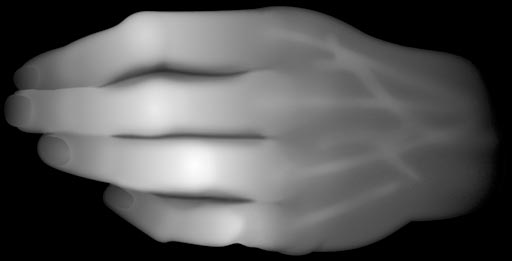
- Adaptive subdivision of polygonal model.
- Height field modeling using a grayscale image to represent elevations (brighter values = higher elevations).
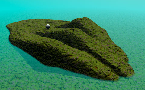
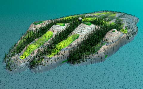
- Two views of the terrain generated from this height field, with different rendering attributes.
return
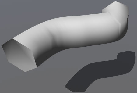
- Influence of smooth shading on the appearance of a polygonal model.
- Flat-shaded rendering.

- Smooth-shaded rendering with the correct breaking angle (59°, less than the angle between the sides of a regular hexagon).
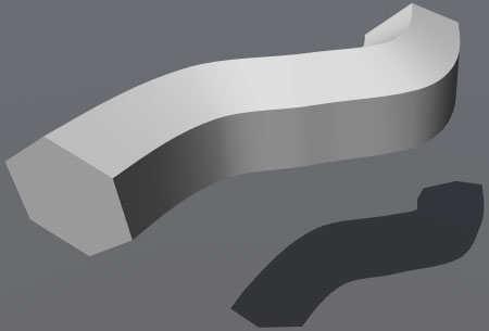
- Smooth-shaded rendering with excessive breaking angle (85°).
return
- The red ribbon represents the path followed by the camera (the blue pyramid) as it animates. The blue dots are the control points used to shape the path.

- Rendered animation.
return
Information specific to the ACG Lab
- The application Art of Illusion is in the 3D folder on the startup drive.
- Documentation on Art of Illusion is available on the ACG lab file server, in the ACG_DOCS volume.
- The Art Computer Graphics program of Fullerton College offers several classes covering 3D topics,
ACG104: 3D modeling and animation for beginners,
ACG120: advanced 3D modeling,
and ACG150: advanced 3D animation.
Look them up in the class schedule.
return
|
previous tutorial |
return to top |
next tutorial |