|
previous tutorial |
ACG home |
Instructor home |
Class home |
List of tutorials |
next tutorial |
Before beginning the project
- If you are working in the ACG Lab
click to read these important notes before you start the tutorial.
This section of the directions contains information that pertains specifically to the way the ACG Lab operates. It may not apply if you work on the project elsewhere.
- If you need to get for yourself the programs mentioned in this tutorial:
VectorWorks is widely used on the Macintosh for Computer Aided Design (CAD) applications. This type of software is primarily used for dimensional design (i.e., to create blueprints of real objects). It can also be used, however, to create virtual 3D scenes--such as the ones we will incorporate in our web pages.
Since the 3D marketplace is very fragmented, VectorWorks is not the only 3D programs you will encounter.
It does, however, follow the basic user interface approach used by all the dominant players, and it embodies all the major aspects of 3D work:
modeling, rendering, and animation.
In this first phase of our 3D project, we will use the most common modeling tools: we will start from flat 2D shapes, converting them to 3D using two techniques generally available in all 3D programs: extruding and lathing. Later we will work directly with basic 3D shapes called primitives, combining them using solid operations.
After some initial setup, we can proceed to create the elements in our scene:
Our final product will be a simple scene containing a logo made up of a few text characters (e.g., your initials).
Initial Setup
 Find the VectorWorks application icon and start the program
 If necessary, use File-->New to create a new document. If asked, choose 'Blank Document' from the 'Create Document' dialog.
- Reset the program by selecting File-->Workspaces-->8 Standard.
- A new untitled document window appears.
- Save the new document: File-->Save As, enter any filename you want (this document will not be posted on the web site directly). Make sure to save often as you continue to work.
- Make sure View-->Rendering-->Wireframe is checked.
- Switch to front view, using the menu command View-->Standard Views-->Front.
- The document window will update to show a front view of the model space.
return to top
Lathed Pedestal
- Make sure the 2D Tools palette is visible (otherwise, display it using Palettes-->2D Tools).
- Choose the Polyline tool (the 1st from the bottom in the left half of the 2D Tools palette).
 Make sure the first icon at the top of the document screen is selected (as shown in this picture), so that the tool will draw straight segments. Sometimes the program will erroneously still draw curves. If this happens, click on any of the other 3 icons, then click back on the correct one.
 Draw the profile for the pedestal, using the Polyline tool in a connect-the-dots fashion to create a series of connected straight segments:
- Click near the middle of the grid to establish the starting point of the profile.
- Click to establish additional vertices representing one half of a front view of the pedestal. To constrain the line segments to vertical, horizontal, and 45°, hold down the Shift key while clicking.
- To complete the profile, return to a location vertically aligned with the starting point, and double-click. An example of a completed profile is shown in this picture.
 Choose the 2D Locus tool (the 2nd from the bottom in the left half of the 2D Tools palette).
 Click to place a locus symbol (a white 'X' in a black box) on a corner of the profile. This is used to indicate the axis of rotation (the imaginary line around which the profile swings as it creates the 3D object). This picture shows where to click for the sample profile shown previously.
 Using the selection pointer (the Arrow tool), drag a selection box enclosing the locus and the profile, leaving both items selected.
 Choose the Model-->Sweep command (sweeping is another name used for the lathe operation). The 'Create Sweep' dialog appears, choose the settings as follows:
- Leave the 'Height' and 'Radius' fields as they are (they automatically reflect the size of the current selection).
- Start Angle = 0
- Arc Angle = 360
- Segment Angle = 20
- Pitch = 0
- Press <Enter> to exit the dialog.
 The result is a symmetrical 3-D shape based on the 2-D profile you drew.
return to top
Extruded Type
 Choose the Text tool (the 1st from the bottom in the right half of the 2D Tools palette).
 Click in the document window to indicate the location of the type. Enter text as follows:
- Type a few letters, such as your initials (to keep file size and processing time down, we cannot have a large amount of text).
- When done typing, choose the Arrow tool, leaving the new text block selected.
- Now choose a typeface, size and style from the top three commands in the 'Text' menu. For best results, avoid typefaces and styles with complicated outlines, since this would also drive up the file size and the processing time: sans-serif typefaces such as Helvetica or Avant-Garde are a good choice.
- To allow conversion to a 3-D object, you also need to select a typeface in the TrueType format.
- As the first step in creating a 3-D object, convert the type block to polylines (much like the ones you drew earlier with the Polyline tool) by using the Text-->TrueType to Polyline command.
- The result is a grouped set of polylines in the shape of the original type.
 Ungroup using Organize-->Ungroup. You will see separate selection handles around each letter. Leave them all selected.
- Choose Model-->Extrude.
- In the "Create Extrude' dialog, enter the depth of the 3-D type (e.g., 0.5") in the 'Extrusion' field.
- Leave the other fields at their default values and click OK.
 The extruded type won't look any different in the front view. Change view using View-->Standard Views-->Right Isometric.
 The isometric view lets you see how the pedestal and the type relate in 3-D space.
return to top
Solid Subtraction Walls
- Change the program's configuration by selecting File-->Workspaces-->8 Standard Artlantis 3D.
- Switch to Plan view (View-->Standard Views-->Top/Plan).
- Make sure the '3D Primitives' palette is visible (otherwise, display it using Palettes-->3D Primitives).
- Double-click on the box icon in the '3D Primitives' palette.
 In the dialog which appears next, enter an appropriate size to enclose the entire scene (assuming you sized objects roughly as shown in the previous steps):
- Length = 6"
- Width = 6"
- Height = 5"
- Enter 0 in all the other fields.
- Press <Enter> to exit the dialog.
- Repeat the same process to create a second, narrower and taller box (e.g., 5.5" long and wide, 6" high).
- Switch to the front view (View-->Standard Views-->Front)
- If necessary, use the pointer (Arrow tool) to drag the two cubes so they indicate the inside and outside surfaces of walls and floor surrounding the scene--as shown in this picture.
 Change your view of the objects to better understand how they are positioned:
- switch back to isometric view (View-->Standard Views-->Right Isometric).
- Change the way the objects in the scene are displayed (rendered), from wireframe (objects appear transparent because all the edges are displayed) to solid (View-->Rendering-->QuickDraw 3D Interactive). If the objects do not appear shaded, use View-->Lighting-->Set Sun Position, leave the settings as they are in the dialog that appears, and click 'OK' to turn on the light.
- Verify that the two boxes are one inside the other, the inner one protruding past the top of the outer one.
- Prepare the boxes for solid operations:
- Select the first box and choose Model-->Convert To Mesh. The box will appear much darker.
- Select the second box and apply the same command to it.
 Solid modeling lets you create complex shapes by combining simpler ones. In this case, we will use the inner box to carve out (subtract) a cavity in the outer box:
- Use the pointer (the Arrow tool) to select both boxes at once (click on one, then shift-click on the other).
- Choose Model-->Subtract Solids.
- In the dialog which appears next, click the arrow buttons until the outer box is highlighted by a thick outline.
- Click 'OK' to complete the subtraction.
 The inner box disappears, and the outer box is hollowed out, creating in a single step the walls and floor of a room.
- If the room appears transparent, make sure the 'Attributes' palette is visible (otherwise, display it using Palettes-->Attributes). Use the pop-up menu next to the paint bucket icon to select 'solid'.
 Now you can carve your choice of doors and windows in the walls of the room by subtracting some more boxes:
- Use again the Box tool in the '3D Primitives' palette to insert additional boxes.
- Switch views as necessary reposition them as needed.
- If necessary, use the Obj Info palette (Palette-->Object Info) to resize them .
 Complete the room with solid subtractions:
- Select one of the new boxes, Model-->Convert To Mesh.
- Shift-select the walls.
- Choose Model-->Subtract Solids.
- In the dialog which appears next, click the arrow buttons until the walls are highlighted by a thick outline.
- Click 'OK' to make a 'hole' in the wall.
- Repeat the same process for the remaining boxes.
return to top
Pyramid Roof
 We'll use a 4-sided pyramid primitive for the roof:
- Switch to Plan view (View-->Standard Views-->Top/Plan).
- Double-click on the pyramid icon in the '3D Primitives' palette.
 In the dialog which appears next, choose a 'regular' pyramid (one that comes to a point), then enter settings as follows (assuming you used the measurements in the examples for the previous steps of the project):
- Sides = 4
- Radius of Base = 4.5
- Radius of Top = 1
- Height = 2
- Polygons inscribed
- All remaining fields can be set to zero.
- Press <Enter> to exit the dialog.
 In top (or plan) view, you see that the edges of the base of the pyramid are rotated 45° away from the walls of the room.
 Rotate the pyramid so that its base edges are parallel to the walls:
- Make sure the pyramid (and only the pyramid) is still selected.
- Display the Rotate Object dialog by double-clicking the Rotate Selection tool (the 1st at the top-left of the Editing palette).
 Enter '45' for the angle, click 'OK'
 The pyramid should now align properly with the walls:
- Reposition and/or resize if needed.
- Remember that just because one view shows the correct arrangement, it does not follow that the objects are in the right place in 3D. You need to look at the scene from multiple views.
 Check the vertical positioning of the pyramid:
- Switch back to front view (View-->Standard Views-->Front).
- Switch back to wireframe rendering (View-->Rendering-->Wireframe).
- The pyramid will typically appear in the wrong place (in this sample picture, it is far too low).
- Use the selection pointer (the Arrow tool) to drag the pyramid to the proper location.
 In this image, the pyramid is positioned correctly atop the walls of the room.
 Change your view to get a good idea of the 3D nature of the scene you created:
- Switch once more to isometric view (View-->Standard Views-->Right Isometric).
- Switch again to solid rendering (View-->Rendering-->QuickDraw 3D Interactive).
- Before leaving, make sure your file is saved so you can continue working with it in the next session.
return to top
Notes
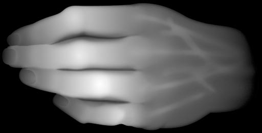
- Adaptive subdivision of polygonal model.
- Height field modeling using a grayscale image to represent elevations (brighter values = higher elevations).
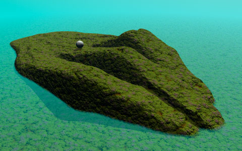
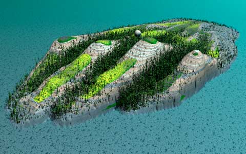
- Two views of the terrain generated from this height field, with different rendering attributes.
return
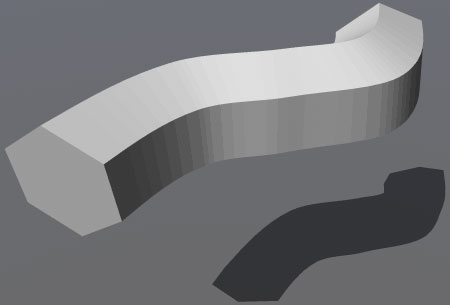
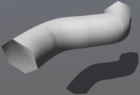
- Influence of smooth shading on the appearance of a polygonal model.
- Flat-shaded rendering.
- Smooth-shaded rendering with the correct breaking angle (59°, less than the angle between the sides of a regular hexagon).

- Smooth-shaded rendering with excessive breaking angle (85°).
return
- The red ribbon represents the path followed by the camera (the blue pyramid) as it animates. The blue dots are the control points used to shape the path.
- Rendered animation.
return
Information specific to the ACG Lab
- The VectorWorks application is in the CAD folder on the startup drive.
- Documentation on VectorWorks is available on the ACG lab file server, in the ACG_DOCS volume.
- The Art Computer Graphics program of Fullerton College offers two classes covering 3D topics, ACG120:
3D Computer Graphics for Macintosh and ACG150:
3D Computer Animation for Macintosh. Look them up in the class schedule.
return
|
previous tutorial |
return to top |
next tutorial |